Long Range Wi Fi Antennas
Bleeding Edge Radio
Digital Audio Tips and Tweaks
Liberation Technology
Brought to you by Amateur Radio AB9IL
High Gain Wi-fi Helical Antenna
A Unique Antenna for Distant 802.11 Connections
Presented here is a versatile, durable, and rather unique wi fi antenna that can greatly extend your wireless networking range and speed. When built with ten or more turns, this helical wi fi antenna vastly outperforms the cantennas and wi fi wok tops often seen on the internet. A short five turn helical makes a very good feeder for a wi fi parabolic dish antenna. A special quality of this antenna is that it radiates and receives a circularly polarized signal. It does not favor vertically or horizontally polarized signals. Thus, this antenna works well with wi fi signals reflecting off of buildings, moving vehicles, or antennas oriented at odd angles. Circularly polarized signals are less affected by rain, so you can reach distant access points in stormy weather. There is a 3 dB loss of gain when using this antenna with linearly polarized signals; high gain is maintained by making the antenna long - at least ten turns for stand-alone usage.
Design parameters for this helical wi fi antenna were calculated using the online helical antenna calculator and was inspired by similar designs used for the AMSAT OSCAR 40 satellite.
PARTS REQUIRED FOR THE WIFI HELICAL ANTENNA:
- one square piece of copper sheet metal or single sided PC board for a ground plane.
- one PVC kitchen drain tailpiece (3.8 cm / 1.5" diameter) to hold the helical windings
- six 1/8" plastic cable ties
- a length of copper circuit tape (adhesive backed, width 3mm or 1/8") or #14 copper wire
- one suitable chassis connector (I used a reverse sma type matching the connector on my adaptor)
- one 90 degree angle bracket with screws and bolts to fit
CONSTRUCTION:
- Center the tailpiece on the PC board, copper side, and mark the circumference in ink.
- Mark four locations on the circumference, spaced 90 degrees, where the cable ties will hold down the PVC tube.
- Mark one location on the circumference, exactly between two 90 degree markings, where the coaxial connector will be mounted.
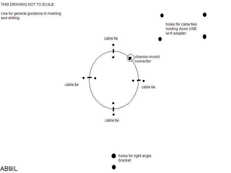
At this point you should have a PC board with a circle in the center, four tick marks on the circle at 90 deg intervals, and one tick mark exactly between two others.
- Drill 1/8" holes on the inside and outside of the circumference at the cable tie locations.
- Drill a hole directly on the circumference suitable for the chassis connector. Carefully measure and drill other holes for this connector if necessary.
- Drill four holes, spaced 90 deg apart near the bottom end of the PVC tailpiece.
- Drill holes to accomodate a small 90 degree corner bracket.
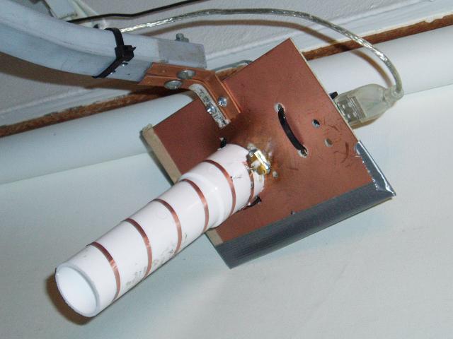
- Drill holes on opposite side of board to accomodate USB wi-fi adapter that will be affixed with cable ties.
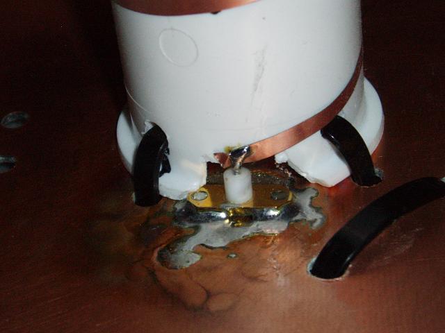
- Tin the copper around the connector mounting hole, then mount the connector. Clip the center pin to keep it only long enough for connection to the helix windings.
- Cut out a notch to accomodate the connector; it should clear center conductor, but avoud cutting out excess PVC material.
- Feed cable ties through from the back side of the board, through holes in the tube, and back through the board. Tighten the cable ties, making sure the tube is firmly held to the copper ground plane.
- Use a ruler and the edge of a sheet of paper to create a template for positioning the windings on the PVC tube. Distance zero represents the ground plane, then add the feedpoint distance, then ticks matching the turns spacing. Use the template to mark your tube on both the feedpoint side and the opposite side.
The objective is to precisely wind the helical wi-fi antenna using an accurate guide...

Space the turns 2.5 cm on a
tube of 3.9cm outer diameter.
Here is a table used for my prototype helical wi-fi antenna and its connector. Note that turn 1 starts at 0.8 cm (height above ground plane of feedpoint). Turns Spacing is 2.5 cm, and the diameter is 3.9 cm (close enough for 1.5" PVC tailpiece). If your connector can be trimmed to allow a feed connection closer to the ground plane than 0.8CM, then simply run the helix as low as necessary. Most impartant is keeping the proper spacing between turns.
|
Spacing=2.5cm Diameter=3.9cm (fits 1.5" PVC tailpiece) |
||
| Turn # |
Height (cm) above groundplane |
Half Turns Height (cm) |
| 1 (feedpoint) | 0.8 | 2.05 |
| 2 | 3.3 | 4.55 |
| 3 | 5.8 | 7.05 |
| 4 | 8.3 | 9.55 |
| 5 | 10.8 | 12.05 |
| 6 | 13.3 | 14.55 |
| 7 | 15.8 | 17.05 |
| 8 | 18.3 | 19.55 |
| 9 | 20.8 | 22.05 |
| 10 | 23.3 | 24.55 |
| 11 | 25.8 | 27.05 |
| 12 | 28.3 | 29.55 |
| 13 | 30.8 | 32.05 |
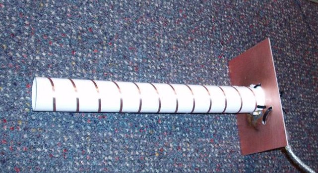
- Carefully wind the helix, using circuit tape or wire, then solder to center conductor of chassis connector. Double check against the turns template. Polarization will be right-handed if the turns spiral clockwise (looking outward from feedpoint).
- Attach the angle bracket and wi-fi adapter, making sure all parts are secure and ready for service, as seen in the images below.
|
|
|
|
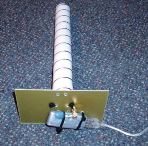
At this point, helical wi-fi antenna is ready for its smoke test...plug in the cables and look for some signals! Theoretical gain of the prototype helical was about 18 dB over an isotropic radiator; it beat my biquad by about 7 to 13 RSSI units, and indeed seemed less sensitive to polarization and rainfall. Signals still seem to fluctuate much from second to second. If your antenna is functioning satisfactorily at this point, I suggest spray painting three layers of clearcoat onto the windings and groundplane for stability and corrosion prevention.